
Smart devices / 塔吊黑匣子
Tower Crane Safety Monitoring System — ZNAO-TG2 Black Box
The ZNAO-TG2 tower crane safety monitoring system (black box) features real-time six-axis sensing capabilities—covering height, trolley radius, slewing angle, load, wind speed, and tilt—along with intelligent alarms for limit violations. It supports automatic networking for anti-collision among tower crane groups and offers eight types of zoning restrictions (including linear, triangular, quadrilateral, and circular areas). Equipped with an industrial-grade display, the system supports 4G and 433MHz communication and includes RS485, LAN, and ONVIF interfaces, enabling connectivity with hook-mounted cameras and integration with management platforms.
Request a technical proposalKey specifications
- capacity
- Tower crane up to 100m+ radius, 5-12 group mesh
- material
- IP67 sensors, cold-rolled host, 11.6in FHD industrial display
- communication
- 4G+433M dual, 485/USB/LAN, ONVIF IPC
- compliance
- Market-supervision special-equipment inspection, housing smart-site acceptance, Linux black-box log
- safety_factor
- Moment overload threshold per load curve, wind 20m/s default
Application overview
Specified around the application
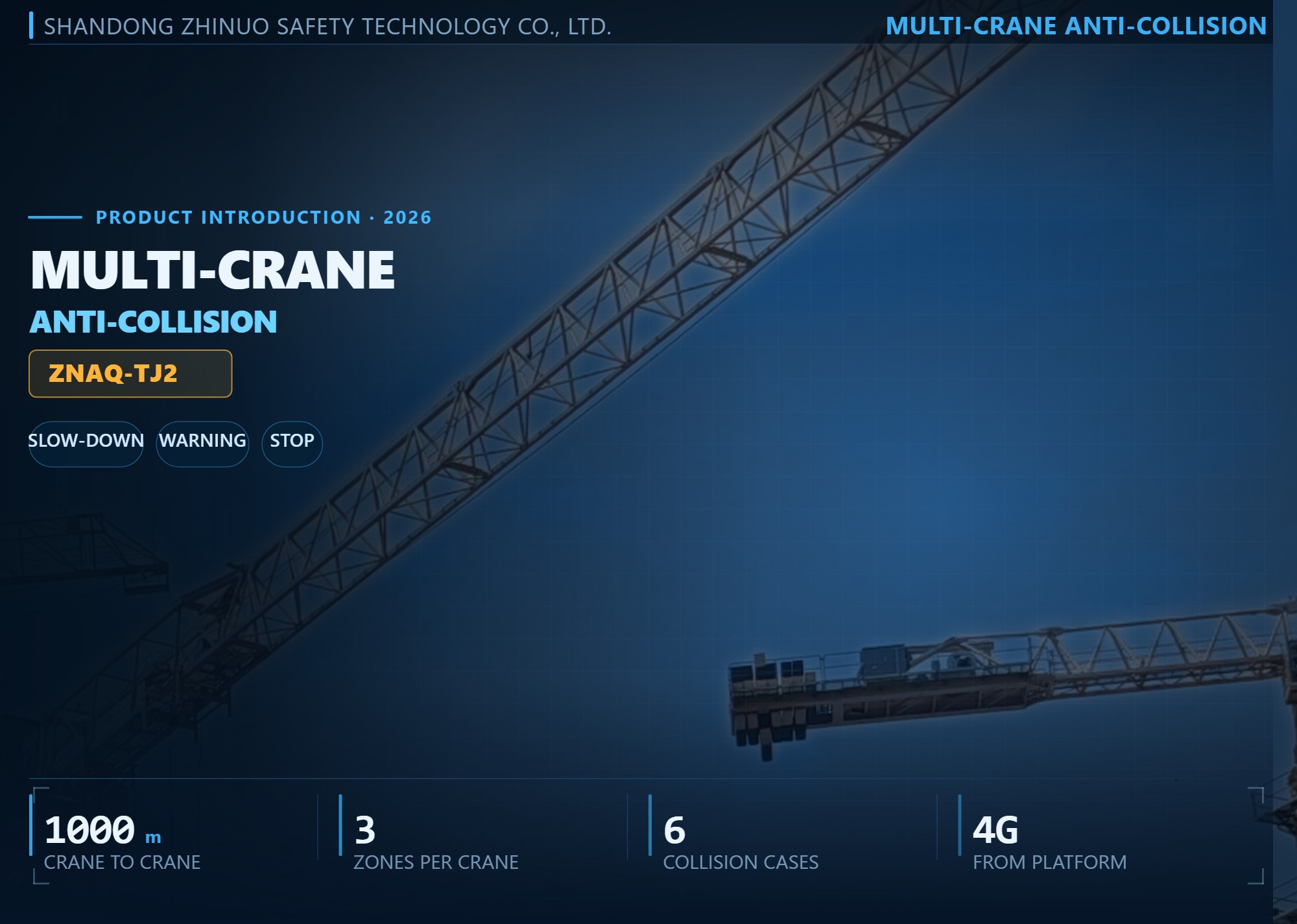 ▌ 01 PRODUCT OVERVIEW · ZNAQ-TJ2
Multi-crane anti-collision for tower cranes
Several tower cranes working one excavation is normal: they share the same footprint, their slewing envelopes overlap, and their jibs sweep the same sky.
From his cabin the driver cannot see when the next jib is coming round, and the other driver cannot see him either — each tower and the buildings between them block the view. ZNAQ-TJ2 turns that from something every driver has to watch out for into something the system handles: the angles of the machines are exchanged live, the zones are worked out from where the jibs are right now, and the warning comes before the contact, not after.
The system does not change the way the crane is driven and does not replace the safety devices already on it. It does two things:
▌ A WORKING-AREA PLAN the live angle of every neighbouring crane, always up to date
▌ A WARNING, THEN A LIMIT at three graded rings
Zones are set crane by crane and re-set whenever the site layout changes.
KEY POINTS
● Angles exchanged crane to crane over 4G wireless, up to 1000 m
● 3 graded zones per crane: slow-down / warning / stop
● Six collision cases covered: same way, opposite, from behind, over-swing, hook into a building, jib into an obstacle
● Site obstacles and overhead power lines drawn on the same plan
● Zones set on the platform, pushed to the cranes over the air
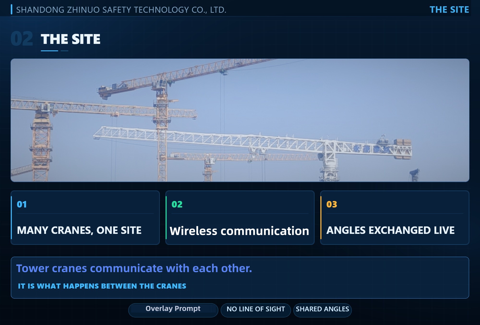 ▌ 02 ON THE SITE · WHY ANTI-COLLISION COMES FIRST
Several towers working one sky
Put three, four or more tower cranes on the same excavation and their slewing envelopes will overlap.
Each machine works out its own working radius from where it stands, and where the next jib is at this moment is not something the driver can see from his cabin. That is the dangerous part of a group-tower site: not that the safety devices are missing, but that they do not know about each other.
Anti-collision is therefore not one more sensor on one crane — it is what happens between the cranes. Each unit shares its angle with the others, every working area is recalculated from where the neighbours are right now, and the margin is called out before it is crossed.
A sensor on a single machine can only see that machine; that is why stand-alone alarms do not solve a group-tower site.
KEY POINTS
● On one excavation, slewing envelopes overlap
● No line of sight to the next jib — talking to each other is not the same as the machines knowing
● Zones worked out from where every jib is now, not from a drawing
● No line of sight needed between the cranes — angles go over the air
● Add a crane or move the site: set the zones again and push them
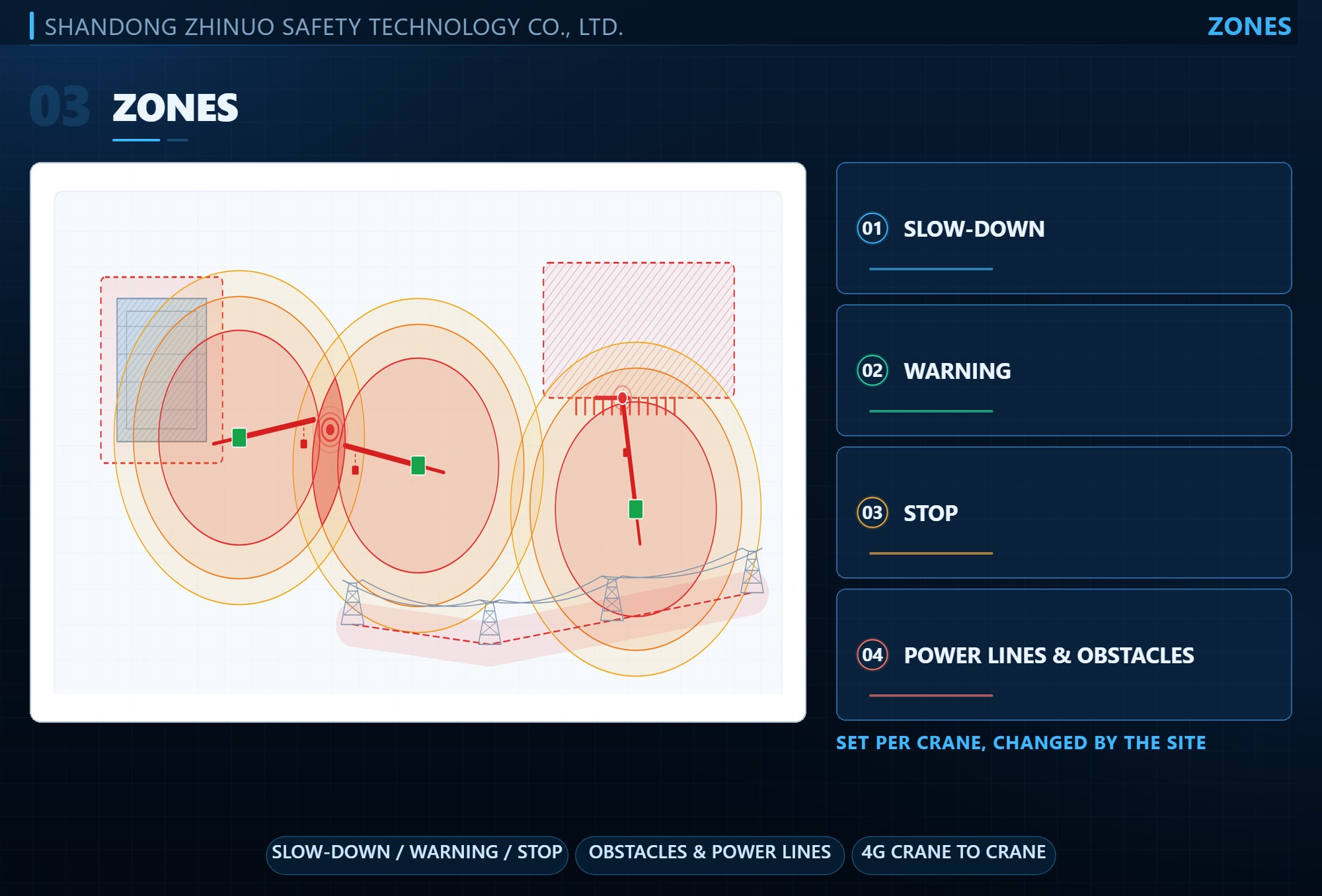 ▌ 03 GRADED ZONES · THREE RINGS
Slow-down, warning, stop — three graded rings
The anti-collision system goes beyond simple “maintain distance” commands.
It establishes three concentric zones around each crane relative to its neighbors:
▌ OUTER RING Deceleration zone a warning as the crane approaches another crane’s operating range, prompting the operator to slow down
▌ MIDDLE RING Pre-warning zone audible and visual alarms in the cab, ample reaction time for the operator
▌ INNER RING Stop zone any further slewing or movement of the crane strictly prohibited
The space between these zones provides operators with critical reaction time.
Buildings, roads, and overhead lines are all marked on the site plan — these are not merely background elements to be ignored; operations must cease immediately upon approaching these physical obstacles.
ZONE CONFIGURATION
▌ PER CRANE configured individually for each crane and adjustable as the site evolves
▌ REAL-TIME BOUNDARIES angular data exchanged over wireless modules up to 1,000 m away, so zone boundaries follow the cranes’ real-time positions
KEY POINTS
● Buildings, roads and overhead lines marked on the same site plan
● Configured per crane, adjustable as the site changes
● Wireless modules: angular data exchanged over up to 1,000 m
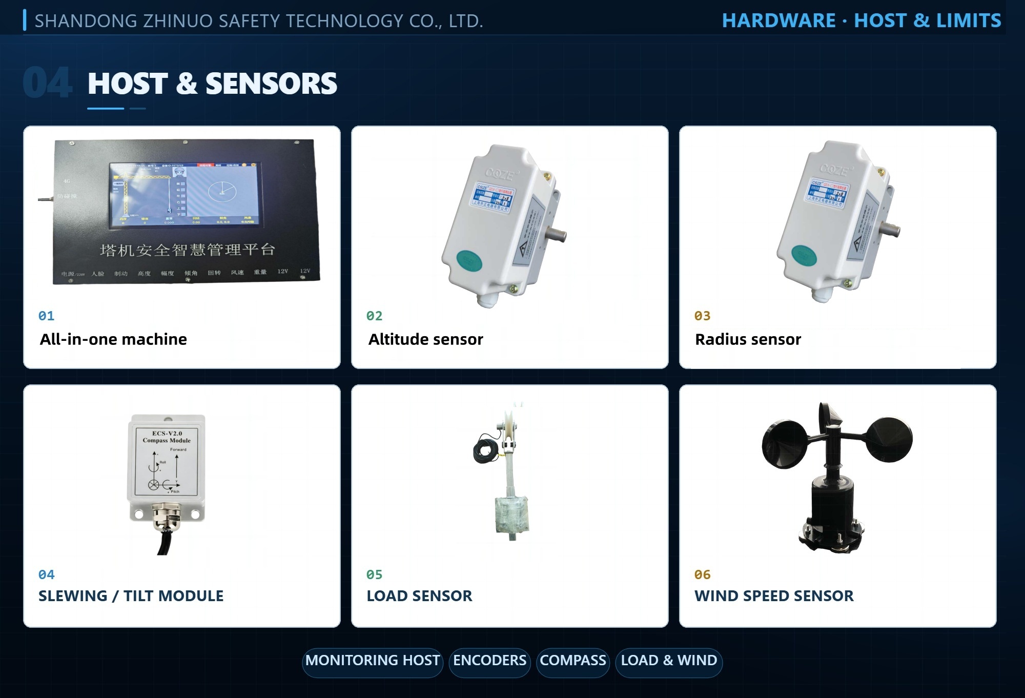 ▌ 04 THE HARDWARE · ONE HOST, EVERY LIMIT
One screen, every dimension of the crane
The in-cab display serves as the system’s interactive interface, plotting the real-time positions of the host crane and surrounding cranes.
This allows the operator to instantly monitor the relative heights and jib slewing status of all cranes. A central processing unit located behind the display processes data — such as height, working radius, slewing angle, tilt angle, load, and wind speed — to generate a real-time operational status map, while simultaneously transmitting readings and warning alerts to the cloud via a 4G network.
SENSORS ON THE EXISTING STRUCTURE
▌ HEIGHT / AMPLITUDE Absolute encoders
▌ SLEWING / TILT Electronic compass module
▌ LOAD Load sensor installed on the hoist rope
▌ WIND Anemometer mounted at the top of the tower mast
These are standard mounting points requiring no drilling, structural modifications, or routine maintenance, and the system requires no additional operator training.
KEY DATA
▌ DISPLAY HD main display cab configuration · AC 220 V / 50 Hz
▌ HEIGHT / AMPLITUDE 0–300 m absolute encoders · 0.1 m resolution
▌ SLEWING / TILT 360° / 0–15° 1° and 0.01° resolution
▌ LOAD / WIND 0–10 t · 0–60 m/s ±5% on load
▌ PROTECTION IP65 sensors on existing structure, maintenance-free after fitting
 ▌ 05 THE PLATFORM · DATA & ALARMS
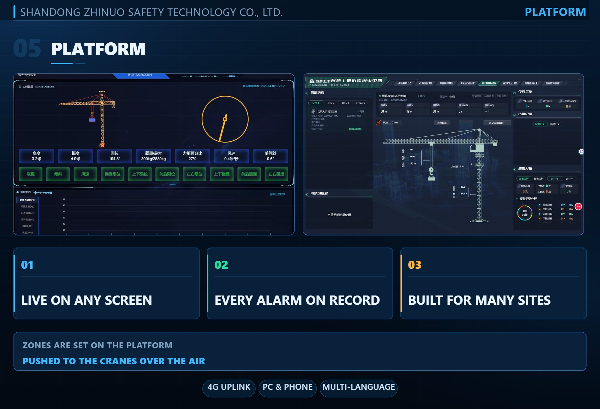
Data in the cloud, every alarm on record
Every crane’s readings and alarms reach the cloud platform over 4G.
The project office watches the whole crane group live on a computer or a phone — which machines are working, which one raised an alarm and at what time, kept one by one and ready for review.
For rental companies running several sites at once the benefit is the most direct: no more climbing tower after tower to collect data.
ZONES AND PLATFORM
▌ ZONES ON THE PLATFORM Slow-down, warning and stop rings drawn crane by crane and pushed to the machines over the air
▌ RE-SET ONCE when the site adds a crane or changes its layout, the zones are re-set once on the platform
▌ MULTI-LANGUAGE the interface ships in multiple languages and is tailored to the target market — ask for a remote demo any time
▌ SAME MAKER platform and host come from the same maker, supported from quotation to on-site commissioning
KEY POINTS
● Live readings and alarms in the cloud, on PC or phone
● Every alarm kept on record, reviewable by time
● Zones set per crane on the platform, pushed over the air
● Multi-language interface, tailored to the market
▌ CONTACT shandongzhinuo@outlook.com WhatsApp +86 176 6371 0314 · en.znaqkj.com
Product gallery
Visual context for configuration review
Next step
Compare related products
Tower crane 3-in-1 visual safety system
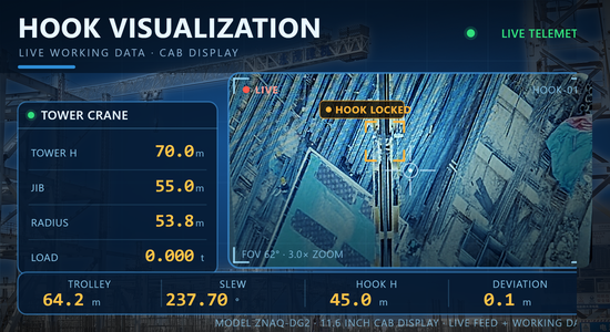
This "three-in-one" visual safety system for tower cranes utilizes a modular industrial platform design and features an 11.6-inch 1080P IPS display unit that monitors load, moment percentage, weight, anti-collision status, working radius, height, tilt angle, and wind speed in real time. It integrates a hook-tracking camera, a 360° panoramic imaging system, in-cab facial recognition, and millimeter-wave radar. The system employs wireless bridge transmission technology (ensuring zero latency), boasts an IP67 protection rating, and operates within a temperature range of -30°C to +70°C. It comes equipped with magnetic sensors (allowing for installation without cutting), a wired mouse, and a 12V in-cab power adapter. Comprehensive technical documentation is provided to meet the requirements for special equipment inspections and "smart construction site" acceptance standards.
Tower crane 3-in-1 visual safety system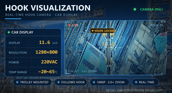
Tower Crane Hook Visualization System
Hook Visualization System — HD along-boom (trolley/boom-tip) camera with auto-zoom streams via low-latency wireless TX/RX to cab display (10.1in 1080P IPS or 7–10in). For tower blind & night lifts.
Tower Crane Hook Visualization SystemNeed documentation or a technical review?
Send the project inputs and we will confirm suitability, configuration, documentation, and delivery options.
Online inquiry
Request a quotation for this product
Describe the application and site conditions, and our engineering team will confirm configuration, documentation, and delivery.